|
|
|
Directorate of Telecommunications
FIELD ORGANISATION
By: A N Holdstock
... continued from Page 1
a. Faulty diagnosis, using a fool-proof indicator system, would be rare.
b. Faults such as complete loss of power supplies at a hill top site would be apparent if a number of tests proved negative.
c. Changing individual units is preferable to changing bays because the chance of two units of the same type failing together is less than the chance of a failure occurring in two bays at the same time. (The standby bay carries similar equipment to the working bay).
d. By checking all systems at frequent intervals or by checking systems in an area as soon as a fire alert occurs in that area, it is possible to rectify a fault before it becomes apparent as a result of an operational failure.
This method would then, in the case of main station equipment, become FIRST LINE SERVICING, to be followed by second and third line in the same way as with mobile equipment.
Systems Problems
The two major maintenance problems with which we are concerned are together responsible for more communications failures and complaints than all other faults put together.
Phase of Incoming and Outgoing Channels
This problem is applicable to multi-station schemes only. All sounds are produced by vibrations which can be passed on in the form of a pressure wave in the air.
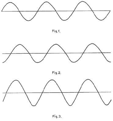
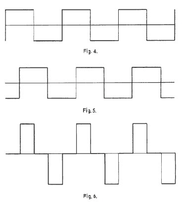
Electrical replicas of these waves can be produced by using a device such as a microphone, and these electrical waveforms can be depicted as shown in diagrams I to 6
Figures 1, 2 and 3 for instance might illustrate the sounds made by a flute, and are waveforms composed of one frequency only and known as sine waves. Figures 4, 5 and 6 do not have their origin in any instrument but are complex waveforms in that they contain the basic frequencies of waveforms 1, 2 and 3 plus an infinite number of harmonics, or frequencies which are multiples of the basic or fundamental frequency.
The human voice produces sounds which have their origin in the vocal chords and are then modified or altered in form by various changes in the shape of the mouth, to produce letters, syllables, and words. The reason we can hear and understand different letters and syllables is because the waveform of a particular sound is always the same, and vastly different sounds such as the letter "S" and the letter "0" are very different in form whereas the letters "B" and "D" would be somewhat alike. If reproduced on a cathode ray tube and photographed they would, in form, lie somewhere between the waveforms illustrated in figures 1 - 3 and those shown in figures 4 - 6
It follows from this that if the waveform is distorted or altered in any way, then the result of feeding the changed waveform into a loudspeaker would be a different sound, probably not recognisable as the original letter or syllable.
Figures 1 to 6 illustrate one way in which a speech waveform can be altered or distorted. If we take a simple waveform such as that shown in figure 1 and then a second waveform exactly the same in form but coming along a little later ( ie delayed in phase), they would sound exactly the same, because the ear cannot detect the difference in time factor. If these two waveforms are now added together, or combined, the result would be as shown in figure 3. Again the same shape but a little larger in size or amplitude, and somewhere between the other two in time. Once again, because this waveform is the same shape it will sound exactly the same. In other words we have combined two waveforms not in phase (or in step) with one another but no distortion has been produced.
If we now take a complex waveform as shown in figure 4 and another as shown in figure 5 exactly the same in shape but once more coming along a little later, or delayed in phase, (as in the case above), they will sound exactly the same for the reasons given previously. If we now add together, or combine these waveforms, we shall get the one shown in figure 6, vastly different in shape from the other two, and sounding very different. As speech waves are also complex, the same effect is produced when two which are not in step, (or in phase) are combined, and the result is an inability to recognise the letter or syllable.
These waveforms, when transmitted through space as wireless waves or via telephone wires as electrical waveforms or indeed through the air as sound waves, take a certain fixed time to travel between two points. Hence the greater the distance they have to travel, the longer the time taken and if two such wireless waves, travelling from two transmitters to a mobile receiver, have to travel different distances then one will arrive later than the other.
Everyone must have heard the effect when listening to two public address loudspeakers which are not the same distance away. Speech becomes difficult to understand and eventually unreadable. In the extreme case when a signal is delayed by one half cycle or 180°, (and this effect can be produced equally by crossing over one pair of connecting wires), there is complete cancellation of all signals and nothing is heard.
Phasing, and the many problems which can arise, is too complex a subject to discuss in a paper of this length, but the hazards are one of the prices we pay for a multi-station wireless scheme which otherwise has many advantages. Care is taken when a scheme is installed to correctly connect and phase all the inter-connections but there are many reasons, which range from deterioration of equipment to a technician at some time making a reversed connection, why the system can get "out of phase". Checking for this "out of phase" condition can be done in one of two ways:
a, check the overall system in one test
b. check each individual piece of equipment in a scheme.
When it is remembered that use of method b, would involve 80 to 100 checks per scheme it will be realised that this type of test could not be carried out very frequently.
|
|
|
|
|
Because of the havoc which one reversal can cause to a scheme however, the more frequently this test can be carried out the better. Equipment has now been developed at the Directorate's new test equipment repair and development centre at Weyhill, Nr Andover, Hants, and this will enable quick tests to be carried out by maintenance technicians using method a. There is no reason why such test equipment should not ultimately become a part of routine operator testing, but it is certain that the ability to know that "all is well all the time", will result in a vast improvement in the operational efficiency of the scheme.
Stability of Mute Operation on Main Receivers
Automatic gain control - the means by which receiver output is kept constant with varying input - has been in universal use for many years. One of the unfortunate effects of this system is that when no signal is being received a great amount of noise is usually present.
Mute circuits were developed so that operators were not constantly forced to listen to this noise and so that signals were fed through to the operator only when the signal to noise ratio was good enough to make signals readable. Developments to receivers - in which the Directorate has played a part - have made it possible for signal levels of from 0.5 to 1 micro-volt to be readable above noise level, and it is natural that this technical accomplishment should be used in order to extend scheme cover from around 80/85% to almost 100%. It is obvious that reliable communications can only be achieved if the point at which the mute operates can be maintained at a stable level between 0.5 to 2 microvolts depending on the scheme end site.
Before operational equipment can be set up to give a particular performance, the test equipment used for the setting-up procedure must be stabilised at an even better level of performance. To this end the Directorate has recently set up a special test equipment maintenance and calibration centre at Weyhill near Andover. Very special calibration equipment has been installed, but even so the measurement and stabilisation of a millionth of a volt at a frequency of 100 million cycles per second is extremely difficult to achieve, even in a well equipped laboratory.
From this it follows that if special laboratory equipment cannot cope with the problem, even less can operational equipment be so stabilised.
This problem is being tackled by the Field Organisation of the Directorate, and it may be that a new technical approach is needed in order to ensure that worthwhile signals are not excluded by unreliable mute operation. In fact this problem is a good example of the way in which automatic gain control and mute operation, both worthwhile technical developments have assisted the operator but at the same time have contributed to system unreliability.
Although new uses for electronics in the field of communications are constantly being sought, and new control systems built, the basic need for system reliability is often not met. It is the job of the Field Organisation to ensure that maintenance is of the highest possible order, and to look continually for new methods, which will enable basic communications systems to give a more reliable service to the user. Force Communications Officers have done a great deal to improve communications between the maintenance organisation and the force, and it is to be hoped that with suitable training they will be able to play a fuller part in the vital work of maintenance.
Mr Holdstock joined the Directorate of Telecommunications in 1948 after Radar service in the RAF. He served in a number of depots and moved to headquarters in 1969 as a Senior Wireless Engineer in the Field Services section with responsibilities for installation, maintenance and the provision of special communications.
Acknowledgement: Home Office DOT Exhibition 1971 Papers
Phase of Incoming and Outgoing Channels


|
|